DSC26103 In-Wall Switch Guide
Specifications:
- • Power usage: 120V 60Hz input, 1200W or 10A max output.
- • Reporting: the Z-Wave in-wall switch can report wattage energy usage or kWh energy usage to a Z-Wave gateway or controller when requested.
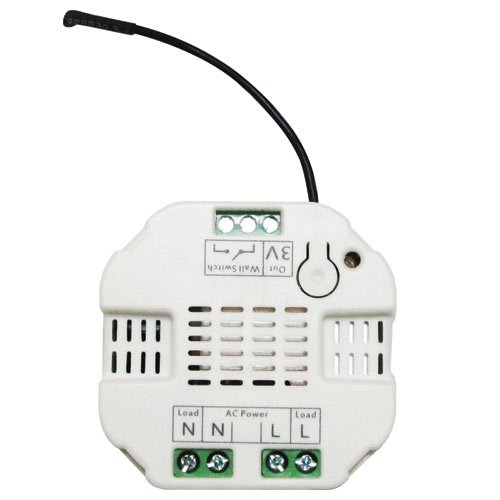
- • Compatibility: the wireless module is powered from the main supply and is a three-wire design which requires a neutral connection. In the event of a power failure, non-volatile memory retains all programmed information relating to the units operating status.
- • Z-Wave repeater: it also is a repeater in the Z-Wave network. Acting as a bridge for communication, it will forward Z-Wave command messages to their destinations if the originating controller is out of range from the destination node.
Installation Steps:
Important: a licensed electrician with knowledge and understanding of electrical systems and electrical safety should complete the electrical installation inside the main circuit box (usually located outside of your house).
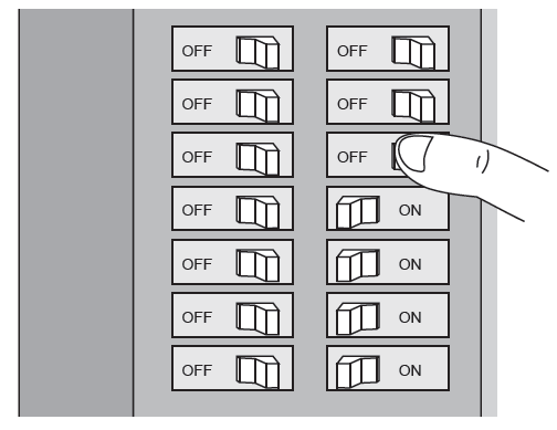
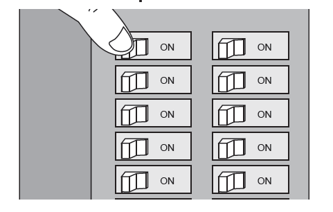
Step 1: Shut Off Power
The electricity to the circuit must be shut off during installation for safety and to ensure that wires are not short circuited during installation thus causing damage to the Micro Module.
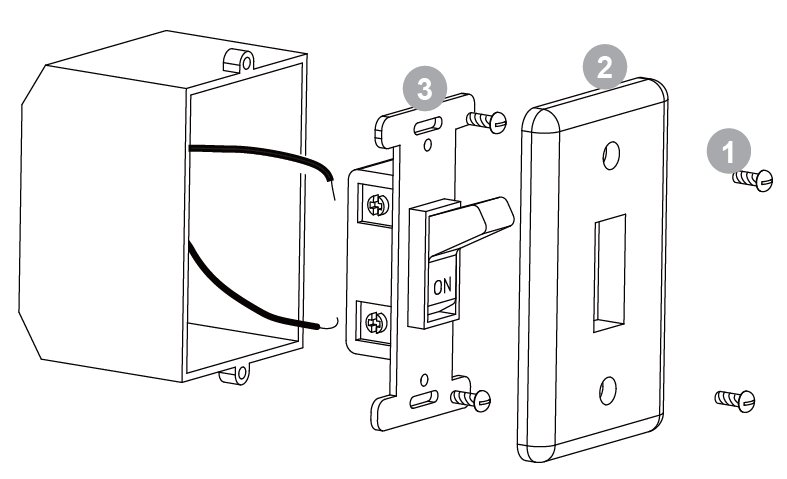
Step 2: Dismounting In Wall Box.
- Remove the two screws securing the cover plate.
- Remove the wall switch cover plate.
- Remove the two screws securing the wall switch to the wall box. Disconnect both wires from the wall switch.
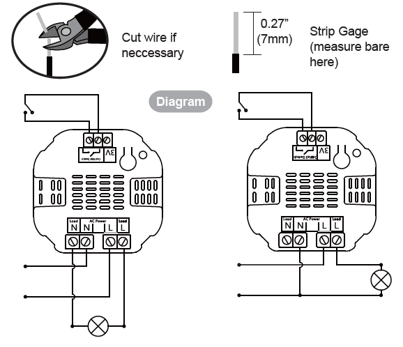
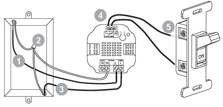
Step 3: Preparing and Connecting Wires
- Live/Hot wire: the black wire is to be connected to the live terminal of the in-wall switch.
- Neutral wire: the white wire must be pulled into the box if not present.
- Load wire: connect to the load terminal of the in-wall switch.
- Signal connection: connect two 18 AWG copper wires to terminals of the in-wall switch.
- Connect the two AWG copper wires to the sides of the main wall-switch.
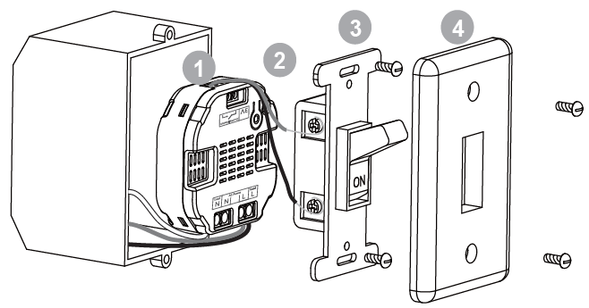
Step 4: Mounting In Wall Box
- Position all wires to provide room for the device. Place the device inside the wall box towards the back of the box.
- Position the antenna towards the back of the box, away from all other wiring.
- Reinstall the wall switch to the wall box.
- Reinstall the cover plate onto the wall box.
Step 5: Restore Power
Restore power at the circuit breaker or fuse.
The Z-Wave in-wall switch must be paired (included) into a Z-Wave network before it can receive Z-Wave commands to turn on/off and report its energy usage. Click here for instructions on how to program the DSC26103 to your panel.