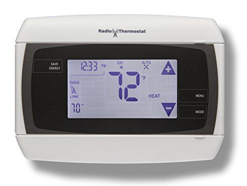
Radio CT32 Thermostat Guide
Specifications:
- Operating temperature: 28° - 122°
- Display: 2.9in x 1.5in LCD with white backlight
- Model: touchscreen
- Power requirements: wire input 12V-25V AC or DC
- Batteries: 4 AA batteries
- Operational lifetime: 15 years
Installation Steps
Wiring Steps:
Warning: to avoid electrical shock and to prevent damage to the furnace, air conditioner, and thermostat, disconnect the power supply before beginning work. This can be done at the circuit breaker.
- Click on the image below which best represents your HVAC wiring. This will take you to your specific wiring instructions, after which you will see a link returning you to the next step.


Mounting Steps:
- Hold the CT32 against the wall, with the wires coming over the top. The CT32 should cover the hole in the wall.
- Attach the CT32 to the wall with the screws provided.
- If you are mounting the CT32 to sheetrock or if you are using the old mounting holes, use the plastic anchors provided.
- Mark first, then drill a 3/16 in. hole for the insert at each screw location, then mount the unit.


Select HVAC Type:
- • Set the HVAC type switch in the Norm position if you have normal natural gas, propane, oil, or electric heat. If you have a heat pump system, set the HVAC type switch to HP. They are located under the top cover on the left.
- • Set the heat type switch in the Gas position if you have normal gas or oil heat or if you have a heat pump with gas or oil auxiliary heat. Put the heat type in the Elec position if you have normal electric heat or if you have a heat pump with electric auxiliary heat.
Install Batteries:
- Install 4 AA alkaline batteries following the marked polarity in the battery compartments. Put the battery in negative end first against the spring, then push the positive end in.

Program Thermostat to Panel:
- The Z-Wave device must be paired to a Z-Wave network before it can receive Z-Wave commands. Click here for instructions on how to add the CT32 to your panel.
HVAC Specific Wiring Steps:
Below are HVAC specific wiring steps, and how each compatible system can connect to the CT32 thermostat as part of installation.
C W RH: 3 Wire Heat Gas Millivolt or 24VAC System:
- Connect the R (or RH) wire to the RH terminal. This connects the heat power.
- Connect the W wire to the W terminal. This connects the heat.
- Connect the C wire to the C terminal. Your heater is now connected to the CT32.

Once you have completed the wiring steps above, click here to return to mounting instructions.
C W RH G: 4 Wire Heat
- Connect the R (or RH) wire to the RH terminal. This connects the heat power.
- Connect the W wire to the W terminal. This connects the heat.
- Connect the G wire to the G terminal on the thermostat. This connects the fan.
- Connect the C wire to the C terminal. Your system is now connected to the CT32.

Once you have completed the wiring steps above, click here to return to mounting instructions.
C W Y RH G: 5 Wire Heat/Cool
- Connect the W wire to the W terminal. This connects the heat.
- Connect the Y wire to the Y terminal. This connects the cooling compressor.
- Connect the RH or R wire to the RH terminal. This connects the power.
- Connect the G wire to the G terminal on the thermostat. This connects the fan.
- Connect the C wire to the C terminal. Your HVAC system is now connected to the CT32.

Once you have completed the wiring steps above, click here to return to mounting instructions.
C W Y RH RC G: 6 Wire Heat/Cool
- Connect the W wire to the W terminal. This connects the heat.
- Connect the Y wire to the Y terminal. This connects to the cooling compressor.
- Disconnect the Rc and Rh terminals by removing RC-RH jumper wire.
- Connect the RH wire to the RH and the RC wire to the RC terminals. This connects power.
- Connect the G wire to the G terminal. This connects the fan.
- Connect the C wire from the heat to the C terminal. Your HVAC system is now connected to the CT32.

Once you have completed the wiring steps above, click here to return to mounting instructions.
C Wn Yn RH G: Multi-stage Heat and Multi-stage Cool
The CT32 can handle up to 2 stages of heat and 2 stages of cool.
- Connect the W, W2 wires to the W terminals. This connects the stages of heat.
- Connect the Y and Y2 wires to the Y terminals. This connects the stages of cool.
- Connect the RH or R wire to the RH terminal. This connects the power.
- Connect the G wire to the G terminal. This connects the fan.
- Connect the C wire to the C terminal. Your HVAC system is now connected to the CT32.

Once you have completed the wiring steps above, click here to return to mounting instructions.
C B or O Y R G: 5 Wire Heat Pump (heat/cool) without Auxiliary Heat
- Connect O wire to the O terminal or B wire to the B terminal. This connects the change-over valve. If you have both O and B, connect only the O wire to the O terminal, and do not connect B to B terminal.
- Connect the Y wire to Y terminal. This connects the compressor.
- Connect the R wire to RH. This connects the power.
- Connect the G wire to the G. This connects the fan.
- Connect the C wire to the C terminal. Your HVAC system is now connected to the CT32.

Once you have completed the wiring steps above, click here to return to mounting instructions.
C O or B AUXn Yn RH G: Multi-stage Heat Pump with Multi-stage Aux Heat
The CT32 can handle up to 2 stages of pump compression and 2 stages of Aux heat.
- Connect O wire to the O terminal or B wire to the B. This connects the change-over valve. If you have both O and connect only the O wire to the O terminal; do not connect B wire to B terminal.
- Connect the Aux 1, Aux 2, to the Aux 1 and 2 respectively. This connects the auxiliary heat.
- Connect the Y and Y2 wires to the Y terminals. This connects the compressor.
- Connect the R wire to RH terminal. This connects the power.
- Connect the G wire to G terminal. This connects the fan.
- Connect the C wire to the C terminal. Your HVAC system is now connected to the CT32.

Once you have completed the wiring steps above, click here to return to mounting instructions.
Best Practices for Thermostat Placement
For replacement installations, mount the CT32 in place of the old thermostat. A new location will require moving your wiring.
For new installations and relocating the CT32, follow the guidelines listed below:
- • Locate the thermostat on an inside wall, about 5 ft above the floor, and in a room that is used often.
- • Do not install it where there are unusual heating conditions, such as in direct sunlight, near a lamp, radio, television, radiator register, fireplace, near hot water pipes in a wall, or near a stove on the other side of a wall.
- • Do not locate in unusual cooling conditions, such as on a wall separating an unheated room, or in a draft from a stairwell, door, or window.
- • Do not locate in a damp area. This can lead to corrosion that will shorten thermostat life.
- • Do not locate where air circulation is poor, such as in a corner, an alcove, or behind an open door.
- • Do not install the CT32 until all construction and painting has been completed.
- • This thermostat does not require leveling.
For additional information relating to your device, click the following link to view the original manufacturer's user guide or installation manual: Radio Thermostat CT32 Manual