How to Program Wi-Fi on the GC2/GC2e Panel
Summary: This guide provides clear instructions on setting up the GoBridge IP Communicator for the GC2/GC2e panel, enabling enhanced network communication for monitoring.
Table of Contents
Clickable links to each section.
- Common Terms
- Specifications
- Factory Default
- Hardwired Ethernet Setup
- Optional Accessories
- Troubleshooting
- LED Status Reference
- Further Assistance
Common Terms
Plain-language definitions of specialized terms relevant to your GoBridge IP Communicator.
- Transformer (Power Brick / Power Adapter)
- The low-voltage power supply that plugs into your wiring to power the device.
- GoBridge IP Communicator
- A device that enables your security panel (like the GC2/GC2e) to connect to your internet router, allowing it to communicate signals over your network via a wired Ethernet connection.
- GC2/GC2e Panel
- The main control unit for your 2GIG security system, where you arm/disarm the system and manage connected devices like the GoBridge.
- Firmware
- Software that is embedded into a hardware device, like your security panel or the GoBridge, to control its basic functions and operations.
- Transceiver (e.g., 2GIG-XCVR)
- A device that can both transmit and receive radio signals. In your security system, it allows communication between the main panel and various sensors or modules like the GoBridge.
- Router
- A device that directs internet traffic between your home network and the wider internet. It provides Ethernet LAN ports for wired connections, which the GoBridge uses.
- Ethernet Cable
- A network cable used to connect devices to your router or network switch for a wired internet connection, providing the communication path for the GoBridge.
- LAN Port
- A Local Area Network port on your router or network device used for wired connections to devices like computers or the GoBridge.
- Uplink Port
- A special port on a router or network switch designed to connect to another network device (like a modem or another switch), rather than individual devices like computers or the GoBridge.
- LED (Light Emitting Diode)
- A small light indicator on electronic devices. The GoBridge uses LEDs to show its connection status to the network and the security panel.
Specifications
Device model, power requirements, and other key details for the GoBridge.
- Device Model: 2GIG Go!Bridge IP Communicator (2GIG-BRDG1-900)
- Compatible Panel Firmware: Your GC2/GC2e panel must have firmware version 1.12 or higher.
- Required Transceiver: You need a 2GIG-XCVR or 2GIG-XCVR2 900 MHz transceiver installed in your panel.
- Power Requirements: Uses the included power adapter (transformer).
- Network Connection: Wired Ethernet connection to your router.
- Communication Protocol with Panel: 900 MHz RF.
Factory Default
How to perform a basic reset for the GoBridge, with an immediate warning under the header.
Warning: Resetting erases all settings. You must contact us after a reset to reconnect your device. Call 469-513-8685.
The GoBridge IP Communicator does not feature a user-operated button for a full factory default reset in the way some other devices might. For most issues, a power cycle is recommended:
- Power down the GoBridge by unplugging its power adapter from the electrical outlet.
- Wait for at least sixty seconds.
- Plug the power adapter back in. Observe the GoBridge's LEDs to confirm it powers up and attempts to reconnect (see LED Status Reference).
If a power cycle does not resolve the issue and you suspect a more comprehensive reset or re-configuration is necessary, this typically involves reprogramming at the GC2/GC2e panel. Please contact us at 469-513-8685 for further assistance, as this process can affect your system's settings.
Hardwired Ethernet Setup
Step-by-step instructions for connecting your GoBridge using an Ethernet cable.
Follow these steps to connect your GoBridge IP Communicator to your internet router for a reliable, wired network connection:
- Place the GoBridge near your internet router and an accessible power outlet.
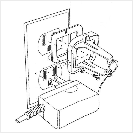
- Connect the included power adapter to the GoBridge unit and plug the adapter into the electrical outlet. We recommend you use the plastic securing bracket (if included and desired) to help keep the adapter firmly in place.
- Upon powering up, observe the GoBridge. Initially, both LEDs on the device should illuminate solid red, indicating it has power but has not yet established network or panel connections.
- Take a standard Ethernet cable (you will need to provide this cable if one was not included with your GoBridge) of sufficient length. Connect one end of the Ethernet cable to the Ethernet port on the GoBridge.

- Connect the other end of the Ethernet cable to an available LAN (Local Area Network) port on your internet router. Avoid using ports labeled "WAN," "Internet," or "Uplink" on your router for this connection.
- Once the GoBridge is powered on and the Ethernet cable is securely connected at both ends, allow a few minutes for the device to boot up and attempt to establish a connection with your network and then with the security panel. The LED lights on the GoBridge will change status to reflect this process. Please consult the LED Status Reference section for an explanation of the light patterns.
- After the GoBridge's LEDs indicate a successful network and panel connection, the final step is to ensure it is correctly programmed into your GC2/GC2e security panel. This is a critical configuration performed through the panel's installer programming menu. If you are unsure how to do this, refer to your panel's installation manual or contact us for assistance.
Optional Accessories
Information on what's included with your GoBridge and what else you might need.
The 2GIG Go!Bridge IP Communicator (model 2GIG-BRDG1-900) typically includes the following essential components for its operation:
- The GoBridge IP Communicator unit
- A power adapter (transformer)
- A plastic securing bracket for the power adapter (its inclusion may vary)
You will need to provide your own standard Ethernet cable. Ensure it is of sufficient length to comfortably reach from your GoBridge's location to an available LAN port on your router.
There are no other specific optional accessories marketed by 2GIG specifically for enhancing or modifying the GoBridge IP Communicator itself.
Troubleshooting
Symptom-based fixes for common GoBridge issues related to power, network, or panel communication.
GoBridge Has No Power / LEDs Are Off
- Check Power Connections: Ensure the power adapter is securely plugged into a known working electrical outlet. Confirm the adapter's connector is firmly seated in the GoBridge unit.
- Test Outlet: Plug another device (like a small lamp) into the same electrical outlet to confirm the outlet is providing power.
- Inspect Adapter & Cable: Check the power adapter and its cable for any visible signs of damage, such as cuts or frays. If damaged, do not use it and contact us for a replacement.
- Outlet Switch: If the outlet is controlled by a wall switch, ensure the switch is in the ON position.
Top LED (Network) on GoBridge is Solid Red or Blinking Green Continuously
- Verify Ethernet Cable Connections: Make sure the Ethernet cable is securely plugged into the GoBridge's Ethernet port and also into an active LAN port on your router. Listen for a click to ensure it's seated.
- Check Router Status: Confirm your internet router is powered on and that your internet service is operational (check if other wired or wireless devices on your network can access the internet).
- Try a Different Ethernet Cable: A faulty Ethernet cable can prevent connection. If available, test with a different, known-good Ethernet cable.
- Try a Different Router LAN Port: Occasionally, a specific port on a router might malfunction. Try connecting the Ethernet cable to a different available LAN port on your router.
- Reboot Network Equipment:
- Power off the GoBridge by unplugging its power adapter.
- Unplug the power from your modem.
- Unplug the power from your router.
- Wait for at least sixty seconds.
- Plug the power back into your modem. Allow it to fully initialize (usually 1-2 minutes, until its status lights are normal).
- Plug the power back into your router. Allow it to fully initialize (usually 1-2 minutes).
- Plug the power back into your GoBridge. Allow several minutes for it to attempt connection. Refer to the LED Status Reference.
Bottom LED (Panel Communication) on GoBridge is Solid Red or Blinking Green Continuously
- Check Panel Power: Ensure your GC2/GC2e security panel is powered on and functioning correctly.
- Verify Transceiver Installation: Confirm the 2GIG-XCVR or 2GIG-XCVR2 900 MHz transceiver is correctly and securely installed inside your GC2/GC2e panel. Refer to your panel's manual if unsure.
- Confirm Panel Firmware: Your GC2/GC2e panel must have firmware version 1.12 or higher. You can usually check this in the panel's system information or installer toolbox menu.
- Check Panel Programming: The GoBridge must be correctly enrolled and configured within the security panel's installer programming. If settings are incorrect, or if the GoBridge was not properly "learned" by the panel, it will not communicate. You may need to consult your panel's installation manual or contact us to verify or redo these programming steps.
Panel Not Communicating Online After GoBridge Setup (No Signals Received by Monitoring Station)
- Verify GoBridge LEDs: The first step is always to check both LEDs on the GoBridge. Refer to the LED Status Reference. For successful communication, ideally both LEDs should be solid green. Address any LED issues first.
- Review Panel Programming Again: Even small errors in the panel's programming for the IP communicator (such as account numbers, receiver numbers, or enabling the correct communication path) can prevent signals from being sent. Carefully re-verify all related settings.
- Router/Firewall Settings: Although uncommon for typical home networks, very restrictive router firewall settings or specific network configurations could potentially block outbound communication from the GoBridge. If you have a complex network setup or have recently made changes to your firewall, ensure the GoBridge has a path to communicate out to the internet on the necessary ports (consult monitoring provider for port details if suspected).
- Test with Monitoring Station: After checking the above, you may need to place your system in test mode with your central monitoring station and send test signals to confirm if they are being received.
LED Status Reference
Meanings of LED patterns on your GoBridge and corrective actions you can take.
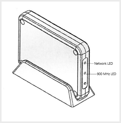
Your GoBridge IP Communicator has two LED lights: the top LED indicates its connection to your network (Network LED), and the bottom LED shows its communication status with your security panel (Panel LED).
Further Assistance
Contact information for more help if you need it.
We hope this guide has helped you understand and set up your GoBridge IP Communicator. If you've gone through these steps and still need more help, please do not hesitate to Contact us at 469-513-8685.